Smartening up a Whole-Home Humidifier
Everything in HVAC is just 24VAC
TL;DR - Hacking an Aprilaire steam humidifier into doing time-of-use electricity pricing
TL;DR #2 - A smart thermostat is just a handful of relays, a sensor, and a radio chip.
Utah air is very dry, so we have an Aprilaire Model 800 steam humidifier paired with the Aprilaire Model 62 digital humidistat. It’s great! I don’t shock every light switch I touch anymore.
But it also draws a ton of power: 11.5A @ 240V, so almost 3kW, because it is literally boiling water to inject into the furnace airstream. We recently switched to a time-of-use electricity rate in which on-peak power is 5x the cost of off-peak, so there’s a big incentive to only have the humidifier run during off-peak hours. But the humidistat is too dumb to have a sense of time, let alone electricity pricing. Let’s fix that.
The Aprilaire 800 Steam Humidifer and its Controls
I crossed switching the power to the humidifier itself off the list pretty fast. While it would be possible to hack something up with a 240V relay, 1) I didn’t really want to mess with the risk of wiring and switching 3kW and 2) I wasn’t quite sure if it was good to regularly switch the humidifier itself on and off at the mains, especially if interrupting a humidification cycle. So, I looked a bit more closely at the controller.
I originally thought the humidistat must have some fancy communication with the humidifer, passing a desired humidity level to modulate the generation of steam, as an analog or a digital signal.
Two rules of thumb for reverse-engineering electronics communications:
- no one invents their own physical layer protocol
- it’s probably the simplest thing you can think of
Hint: it’s digital. It’s not RS-485. It’s not RS-232. It’s just closing a switch - simple on/off control.
A brief primer on standard American HVAC wiring: the furnace electronics have a transformer that supplies 24VAC for accessory devices, like the thermostat; this voltage is provided on a wire called “R” (for…red) or “Rh” (Red-heat). The way a conventional thermostat activates heat, AC, or the fan is extremely simple: it just puts 24VAC onto dedicated control wires for each device (heat on “W” (white), air conditioning on “Y” (yellow), or fan on “G” (green)) by connecting R/Rh to the correct control line. There is also often one more wire (“C”, common) that represents the other terminal on the transformer, so that power can be drawn from the R/C pair if needed. (There can be other control lines, for multi-stage heat or cooling, or heat pump valves, but they all work basically the same way.
Of course, there do exist more modern protocols: “communicating thermostats” use a serial protocol rather than 24V on/off switching. There are various protocols, like OpenTherm (which seems to be mostly a European thing?) and the Carrier Infinity Protocol, which is RS-485 based. These offer finer-grained control than just on/off, which can be useful for more stable temperature control.
But I don’t have one of those, so 24VAC it is!
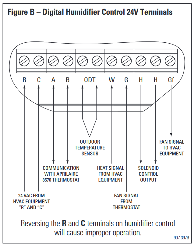
Wiring diagram for the Aprilaire Model 62 humidistat
With that knowledge, it’s a bit easier to understand what’s going on with the humidifier controller wiring. The controller/humidistat needs some power for its own electronics, so it connects to R and C, from which it can draw a 24VAC supply. It monitors W from the furnace, so that it can tell if the heat has been activated (and there’s a likely need for humidification), and hijacks G between the thermostat and the furnace so that it can see if the fan has been activated, as well as activate the fan itself (G comes from the thermostat, and Gf goes to the furnace). The controller shorts the H/H terminals together to signal the humidifier unit that steam generation is desired. (The A/B and ODT terminals aren’t important here.)
The obvious places to attach something to intervene are either at the H/H terminals — interrupting the humidifier calls somehow — or the R/C terminals, yanking power to the controller entirely. The latter is a pretty easy experiment, so I tried disconnecting R while the controller was calling for humidification…and the humidifier stayed “on” but stopped making steam! This seemed like a perfect outcome: no weirdness or danger to the control board from yanking the main power supply, but an effective cut to the call for steam generation, which is what draws all the power.
To be sure, I thought I’d reach out to Aprilaire and ask if pulling power to the controller was a safe thing to do, or whether it would be preferable to interact with H/H, and received the following response:
In theory something like this should be able to work for you, but since it is outside our recommended installation, we do not have a recommended way on how to do so. If installed correctly we do not see this causing a potential issue but since we have not tested it, we can not say for sure that one way is better than the other.
“We do not see this causing a potential issue” is a pretty good blessing. So, how to control these lines?
Remote-switching 24VAC
We have a Hubitat-based home automation system, so I was looking for some way to control 24V over Z-Wave or ZigBee. My first thought was to use a Z-Wave relay like the Zooz ZEN16, and while that would have worked, it would have been a little clunky, as I’d need to wire up not only the furnace 24VAC control signals, but also a separate power supply for the relay and its radio.
And then, a brainwave: a smart thermostat is nothing but a little computer with a radio that happens to be powered from 24VAC, and can switch that 24VAC onto various outputs! So here’s the setup:
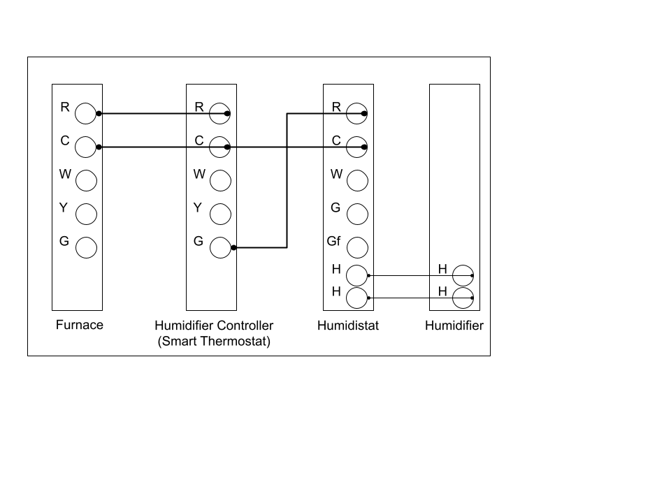
The easiest terminal to use on a thermostat is the fan, or “G”, wire, because it is under purely manual control: if the fan is set to “on”, then the thermostat will bridge R and G (putting 24V on it); if it is set to “auto”, then there is no connection. In theory, one could also use terminals like W or Y, but those are controlled by the internal temperature sensor, so forcing them on or off requires adjusting the set point of the thermostat with respect to the ambient temperature. The wiring diagram above shows the way. I have elided some wiring (from the furnace and the humidistat to the “main” thermostat that actually controls the furnace operation) for simplicity. The short version: R and C go from the furnace to the new “humidifier controller” (really, a smart thermostat). C also goes to the humidistat. G is connected from the controller to the R terminal of the humidistat. Then, when the controller is set to “fan on”, the humidistat is powered (and the humidifier can run); when the controller is set to “fan auto”, no humidistat power means no steam generation.
I set this up with the cheapest ZigBee thermostat on Amazon, the $40 Centralite Pearl, which gets picked up as a generic ZigBee thermostat by Hubitat, and it really works! Setting the thermostat to “fan on” turns on the humidistat, and vice versa, and switching to fan auto during a humidifer call stops the steam, just as expected. It is then simple to set up rules in Hubitat Rule Machine to remotely switch the “fan” state when power enters and leaves peak pricing.
Protip: sometimes the Pearl drops fan state changes, so to be sure, send the commands to turn on or off a few times.
Technical nitpicks
The setup above is probably sufficient, but one interesting corner case is that the humidistat can activate the humidifier either when the furnace and fan are already running, or, if it detects sufficiently low ambient humidity, can actually call for the furnace fan to run on its own and then activate the humidifier. If power is yanked from the humidistat, it both turns off the steam generation, and is unable to call for the furnace fan to run (remember, that’s also nothing more than switching 24V onto one wire). The potential problem is that while the humidifier’s electrodes will de-energize, there is probably still some residual steam coming out of the box, and it’s probably not great to have steam sitting around condensing inside the furnace outflow duct. To avoid this, the Hubitat rule checks to see if the furnace was already forced on when turning off the humidifier, and if not, first turns on the fan, then turns off the humidifier, and lets the fan run for three minutes to purge any remaining steam.
The other open question is whether it would be possible to bypass the humidistat entirely. While it generally works well, its settings (“1” - “7”) are opaque in their implications, and more sensors are available to the Hubitat controller that in principle could be used for even tighter control of humidity. The Aprilaire 62 activates the Aprilaire 800 humidifier by shorting the H/H wires that run between the humidistat and humidifier. It would probably be possible to control this in parallel with the smart thermostat. The description of HVAC wiring above was simplified. In fact, most thermostats support two independent 24VAC sources, labeled Rh and Rc, in case different transformers are used to power heating and cooling controls, and by default will simply short these two terminals together for the common case of one transformer. I have not tried this, but I believe that if Rh and Rc are not bridged, then the connection-state diagram looks like this:
- call for heating: W connected to Rh
- call for fan: G connected to Rh
- call for air conditioning: Y connected to Rc
If this is the case, then it should be possible to add a parallel pair of wires from the humidifier H/H terminals to Rc and Y on the smart thermostat, enabling the following state space:
- thermostat fan off, AC off: humidifier off
- thermostat fan on, AC off: humidistat automatic control
- AC on: humidifier forced on
To force the AC on would require setting the thermostat into cooling mode and ensuring the set point is well below the ambient temperature.
However, this seems like it would come at some risks. The humidistat is set up so that the humidifier cannot be activated without the furnace or furnace fan running at the same time, so that steam is not constantly injected without any airflow through the ducts. This behavior could be emulated in software by the home automation, but the risk of dropping a command or otherwise failing to atomically activate-fan-and-humidifier or vice versa seems high enough that it’s not worth creating trouble — at least not right now.
Conclusion
Being able to control the humidifier with one cheap thermostat and a couple extra wires is both simple and makes the ROI quick. Assuming the humidifier ends up running the same amount of time, just delayed to off-peak rather than on-peak, it only takes about 67 hours of humidifier peak-hour runtime for this $40 setup to pay for itself arbitraging 75c/hr operation into 15c/hr operation — probably less than a month, given 7 peak hours per day.
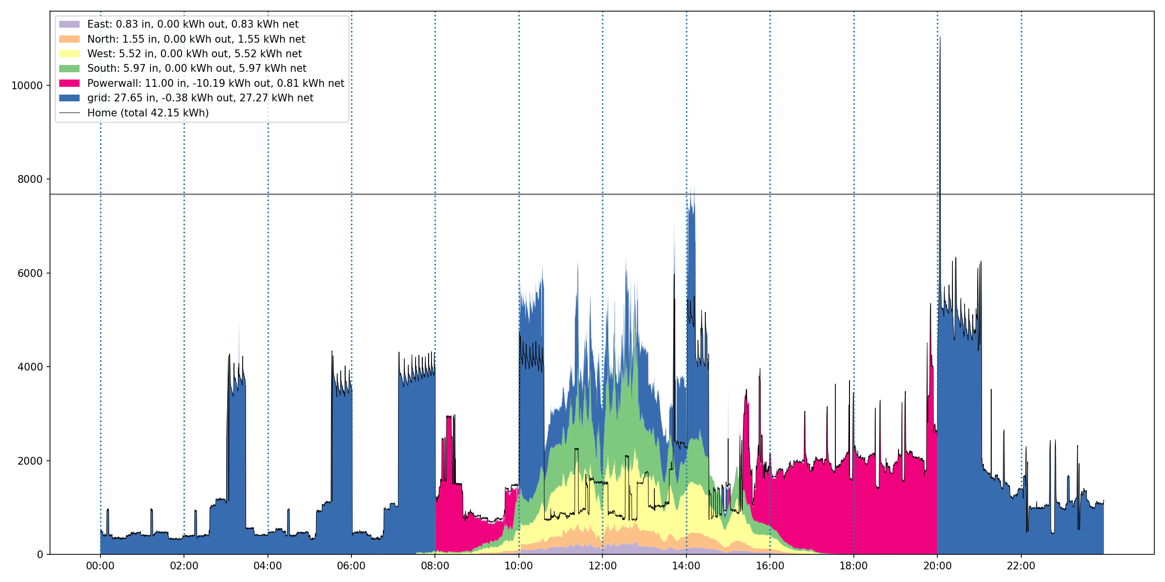
I’ve now been using this setup for about six months, and other than thermostat occasionally dropping a message (easily fixed by sending the “fan on” or “fan off” commands three times), it’s been rock-solid. The plot below, of power draw for our house on some random day, shows the effect. The black line represents the house’s power draw, blue fill is power drawn from the grid, pink is power from the Powerwall (filling in during peak hours), and the other colors are solar. When the humidifier is active, there is a very distinctive sawtooth pattern at around 3-4kW total draw. You can see quite clearly where the humidifier turns off (though the heat is still running) at 8am when electricity goes to peak pricing, and where it turns on at 8pm when peak pricing turns off in the evening.
Putting the wires on a mechanical timer may have been a somewhat simpler approach (though, really, not THAT much cheaper), but having the humidifier hooked up to Hubitat has enabled a range of other automatic control. In addition to control based on electricity rates, I’ve also put in rules to disable the humidifier when:
- the humidity at certain indoor sensors rises above a critical point (the humidistat’s sensor is located quite far away from those rooms, in the return airstream; controlling room humidity directly is a better way to minimize condensation).
- we’re away from the house for an extended period of time
- our power goes out and the house goes on backup (through another Hubitat interface to our Powerwall)
Overall, this was easy to set up and program, super reliable, and super useful. Definitely one of the better automation projects I’ve bothered with. As always, drop questions or comments on Twitter @ImranSHaque or Mastodon @ihaque@genomic.social!