PeloMon: Hardware (Part III)
Enough fooling around, show me the board!
TL;DR - Hardware selection (microcontroller, power delivery, signaling) and board layouts for the PeloMon.
Fourth in a series. See the project GitHub, to be updated through the series.
- Part I: Decoding the Peloton
- Part Ib: How does the Peloton compute speed?
- Part II: Emulating the Peloton
- Part III: PeloMon Hardware
- Part IV: PeloMon Software
Selecting the hardware
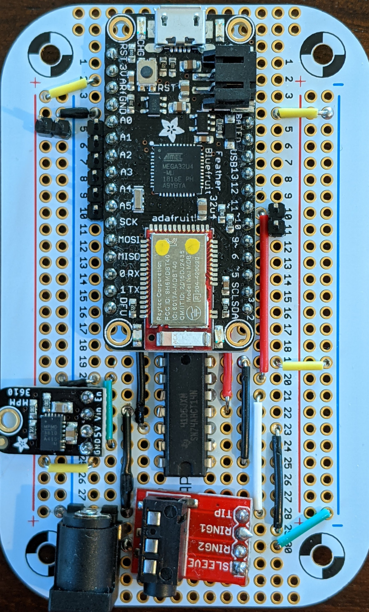
Let’s walk through the parts on the board from top to bottom.
Microcontroller: Adafruit Feather 32u4 Bluefruit LE
The most important decision was to choose the controller at the heart of the project. ptx2’s post on unbricking a Flywheel bike inspired this work, so an obvious place to start would have been the same Raspberry Pi Zero W that was used in that project — easy to follow in the footsteps and use the same software stack! However, I went in a different direction for a few reasons:
- the Pi only supports a single serial interface in hardware. This was fine for the Flywheel, but the PeloMon needs two interfaces to see everything that’s going on — one for the HU and one for the bike. A little Googling suggested that getting tight enough timing on the Pi to bit-bang serial reception reliably on the GPIOs was difficult and flaky, and I didn’t want to get a separate USB UART to add ports.
- No insult to ptx2, but the gymnasticon project was written in Node.js with the noble and bleno libraries…and, well, Node.js is cancer. (Which is to say, I’ve used Node and prefer not to work in Javascript unless I have to. Everyone’s got aesthetics and those are mine.)
- Working on a full Linux system with gigs of storage and a GHz+ processor felt like huge overkill for what I needed this thing to do, and I felt like a more constrained environment would be more fun. My day job involves very high-level code; writing low-level stuff is fun too.
The board also had to support the wireless interfaces I cared about! For a speed/cadence sensor to pair with a Garmin watch, you have a choice of Bluetooth LE (BLE) or ANT+. It’s a lot easier to find BLE hardware than ANT+ hardware, so that’s that. This would be powered off the power supply for the bike itself, so low power was not a consideration.
Based on the BLE constraint, the desire for a constrained environment, a need to implement two serial interfaces, and my own microcontroller experience, I focused my search on Arduino-compatible devices (I knew it was easy to implement multiple software serial interfaces here). There are a variety of Bluetooth shields available for Arduino, but most do not support Bluetooth LE, which is a different spec from just “Bluetooth”. Several all-in-one boards do support BLE: the Arduino Nano 33 BLE and the Adafruit Feather (M0/32u4/nRF52) Bluefruit LE boards (among others, I’m sure). All of these boards have a chip from Nordic Semiconductor on them handling Bluetooth; some of them (the M0 and 32u4) have separate microcontrollers running your code, whereas the others use the Nordic chip also as the main microcontroller.
I chose the ATMega 32u4-based Adafruit Feather 32u4 Bluefruit LE mostly because I knew that I wanted to maintain the resistance calibration table- in non-volatile memory, and I knew that could be done reasonably with the EEPROM support on the ATMega whereas I’m not familiar with how well that’s supported on the Cortex-M0 or nRF52832 boards. (There are libraries that use the onboard flash on the Cortex boards to emulate EEPROM, but the underlying memory has serious write endurance limitations that I don’t really want to have to think about; the ATMega EEPROM has endurance at least 10x better, perhaps more.) This also meant I was working on the most limited platform of all of them - with only 32ish kB of code space.
Surrounding logic: level shifter and power
As described in the first post in the series, the Peloton’s signaling is inverted RS-232 at a voltage of about 5.5-6V. The ATMega chosen above is a 3.3V part which has dire warnings about applying input voltages greater than that to any pins — and would probably be even less happy with voltages below ground. Full-on UART chips are expensive, so I used a cheap 74AHCT14N inverter/level shifter between the wire and the micro. Strictly speaking, it too is being driven outside its specifications, but it seems to work fine and hasn’t let out any magic smoke yet.
We also need to power this board. The Feather is designed to be powered from USB or from a lipoly battery, but there’s no USB port convenient on the back of the Peloton and there’s no reason to add a battery to the BOM. The tablet has a 12V supply that we can split off, but then this needs to be dropped to the right voltage for the hardware. The power management documentation for the Feather says that the board is not designed to take an external power supply, which is probably its biggest disadvantage in this application. Nevertheless, it is possible to power it from an external source by applying power directly to the appropriate pins.
I first tried to do this with a 3.3V buck converter…and it didn’t quite work. Looking at the power delivery schematics for the board, it’s unclear why, but swapping it out for a 5V buck converter with its output wired to the USB power pin made it all work fine. This has the possibility of back-powering the USB port if connected to external power and USB at the same time…so don’t do that.
Assorted Bits
Power comes into the board using one of Adafruit’s “breadboard-friendly” 2.1mm DC barrel jacks. This thing may be breadboard-friendly, but in my opinion it’s breadboard-useless: the pins’ offsets are just slightly off from where they’d need to be to go straight into a breadboard (they need to be bent slightly), and they’re not long enough to be properly held on, at least in the breadboard I used. It would kinda stick, but not very well. It was fine when soldered in, though.
The TRRS jack and breakout was just a standard TRRS breakout. Nothing special and they come ten to a pack for cheap. Ditto the precut breadboard wires; a couple bucks to have convenient lengths is well worth it.
While prototyping the PeloMon I built it on a standard half-size breadboard. For the final thing, I moved it to the Adafruit mint tin-sized PermaProto board, which has the same connection pattern as a breadboard, with a few extra rows of isolated spaces, and the right size to fit into an Altoids tin. I probably could have gotten away with something cheaper, but this was thrown in for free with a sufficiently-sized order, so why not? It’s nice.
Board layout
There’s nothing tricky about laying out this board — no high voltage isolation, no sensitive timing, etc. — other than a fun puzzle figuring out where to put components to optimize wiring. A couple months ago, we had a freak windstorm in Salt Lake City that knocked out our power. Playing with breadboard layouts in pencil and paper while waiting for components to arrive was relaxing:
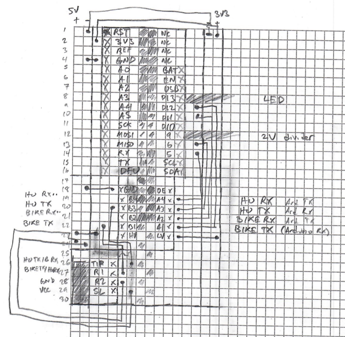
In the end, there were only a couple slightly tricky things about optimizing the layout from a breadboard perspective:
- Several components (the Feather, the MPM3610, and the TRRS) sit on headers making them not quite flush with the board, allowing the routing of wires underneath them. Additionally, in the layout for the Perma-Proto, one wire is routed on the backside of the board.
- The level shifter has six channels, but we only use two of them. The best place to put the buck converter overlaps with the level shifter and would put 12V — well above the maximum ratings for the chip — on one of the pins of the shifter. Since we’re not using most of the channels, though, in the final layout, four of the pins on the 74AHCT14N are clipped, pins 2-5 on the left side. (Zoom in on the picture at top and you’ll see it.)
Schematics and Parts List
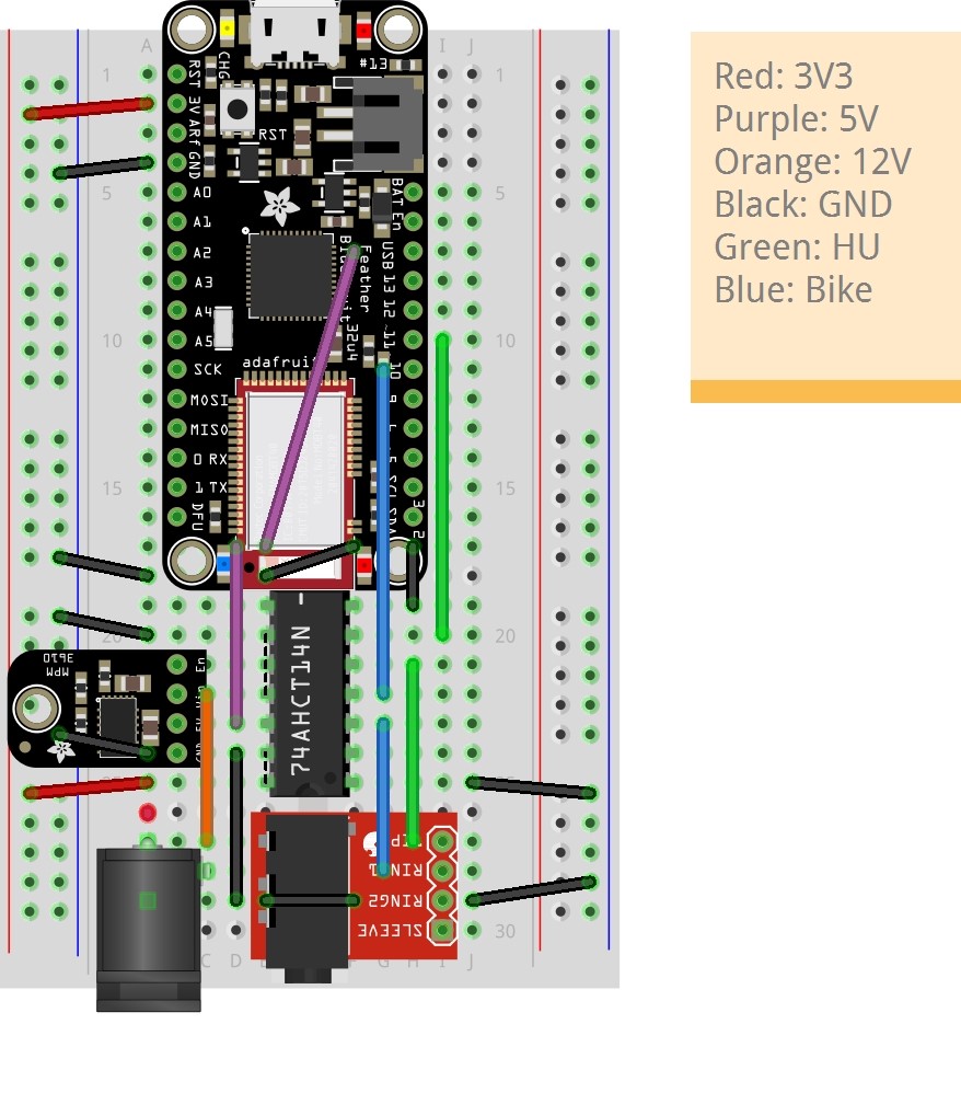
Fritzing files for the breadboard and perma-proto versions of the PeloMon are on the project GitHub. Note that the file for the perma-proto version looks like it’s on a normal breadboard if you load it into Fritzing — that’s because the actual perma-proto layer completely breaks Fritzing’s responsiveness. The coordinates of each piece are still correct.
Here are links to the hardware and tools involved in the project in case you’d like to follow along. I bought from a mix of Amazon and Adafruit; note that the Amazon links are affiliate links so if you end up buying there I’ll get a small referral bonus.
| Part name | Links | Price at time of writing |
|---|---|---|
| PeloMon device parts | ||
| Adafruit Feather 32u4 Bluefruit LE (I recommend pre-soldered headers) | Adafruit Amazon | $32.95 - $34.52 |
| MPM3610 5V Buck Converter Breakout | Adafruit | $5.95 |
| 74AHCT14 Inverter/Level Shifter | Adafruit | $0.95 |
| TRRS breakout board | Amazon | $6.98 (qty 3) |
| 2.1mm DC barrel jack | Adafruit | $0.95 |
| Perma-Proto Mint Tin-Sized Breadboard | Adafruit | $5.95 |
| To connect PeloMon to Bike | ||
| 6” stereo headphone splitter cable | Amazon | $4.91 |
| 3ft aux cable | Amazon | $3.99 |
| 2.1mm DC barrel jack splitter | Adafruit | $2.95 |
| Tools (you may already have these!) | ||
| Soldering iron kit | Amazon | $9.99 |
| Wire flush cutters | Amazon | $7.96 |
| Precut breadboard wires | Amazon | $6.79 |
| USB logic analyzer 24MHz 8ch | Amazon | $12.49 |
| Half-size breadboard | Adafruit Amazon | $5 (qty 1, Adafruit) - $6 (qty 4, Amazon) |
| Extra headers | Adafruit | $0.50 |